Numerical solution for tilted
Hydro-static multi-pad thrust
A. van Beck” and A. Segalt
The effect of the bearing shape functions on the self-aligning action of tilted hydro static thrust bearings of finite length is studied. Furthermore an alternative method is described, to select the restrict-or coefficients, without flow computation. Tilted plane bearing surfaces and laminar flow condition in the film are assumed. Orifice restriction is considered.Numerical results are verified by exact solutions of the infinite bearing length. Copyright
Keywords: Hydro-static, tilt, finite length, numerical
Introduction
AS a alternative for lock gates,equipped with wheels running rails, the latest idea short the ate on a very thin film of water, squeezed between the lock gate and a smooth plastic threshold. The system was used for the first time ever in the lsquo;Orange locks in the river lj in Amsterdam which was completed in 1995. A lock gate with a wear-resistant opening and closing mechanism was realized which needs practically no maintenance.For the lsquo;Oranjestad locks circularly shaped hydro-static bearings have been designed at the trilogy section
numerical solution for tilted hydro static thrust bearings
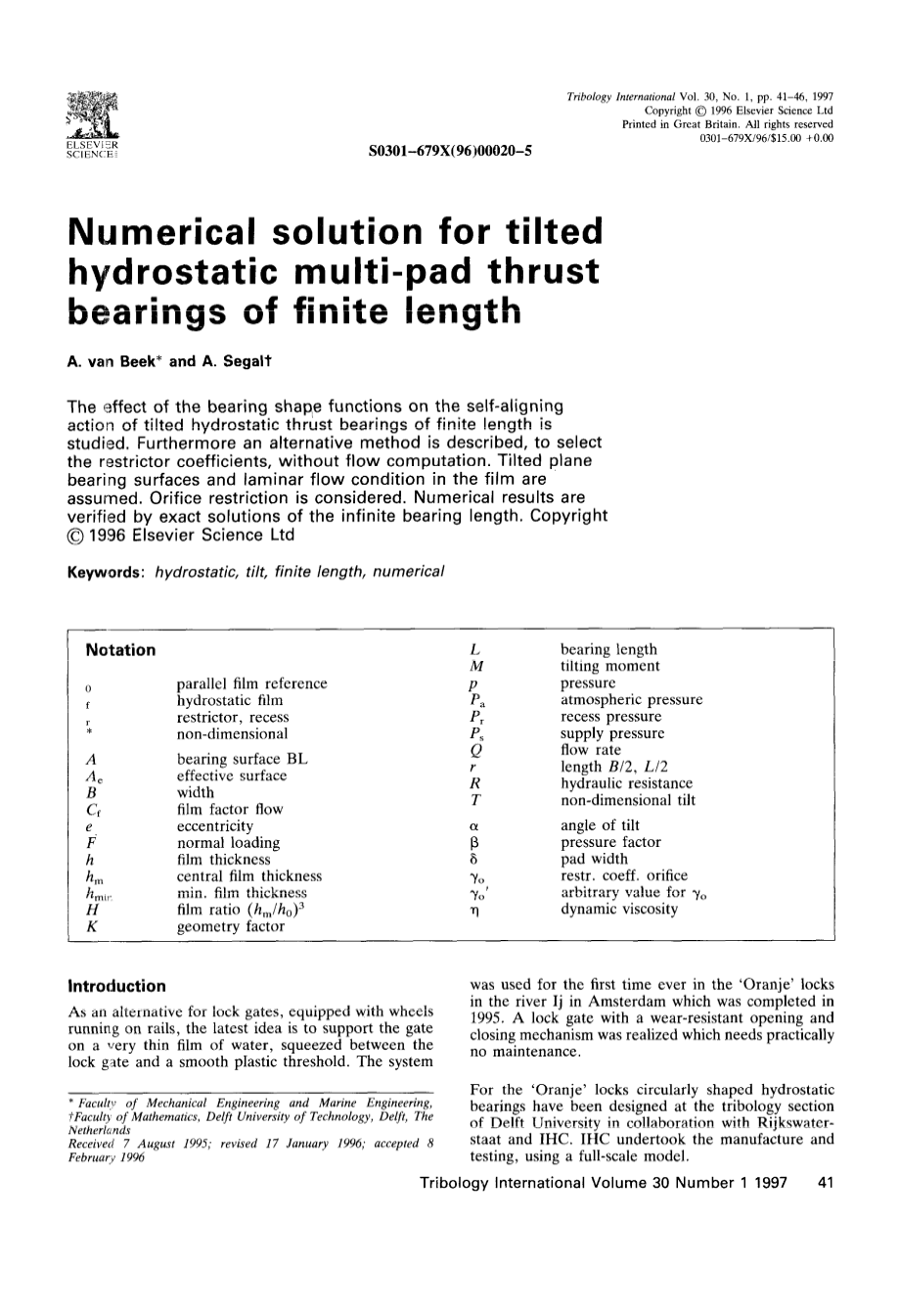
Fig 1 Front view of the lock gale
The second term in this expression represents the end effects; it will vanish with infinite bearing length BIL -- 0. To make the recess pressure dependent on the load each recess is to be fed through a separate flow restrict-or. The quotient of the pressure drop in the restrict-or
— , where P, is the supply pressure (source pressure), and the pressure drop in the film
r lsquo; a S defined as the pressure factor Q:
Two hydro-static bearings are installed on the longitude- The non—dimensional load carrying capacity in a nal axis of the 25 in wide lock gate, one at each end reference configuration U can be expressed as:
of the gate (Fig 1). In the design of the circularly shaped hydro-static bearings only the tilt of the rigid bearing surface has been considered.
A
Two hydrostatic bearings carry a force of 250 kn each
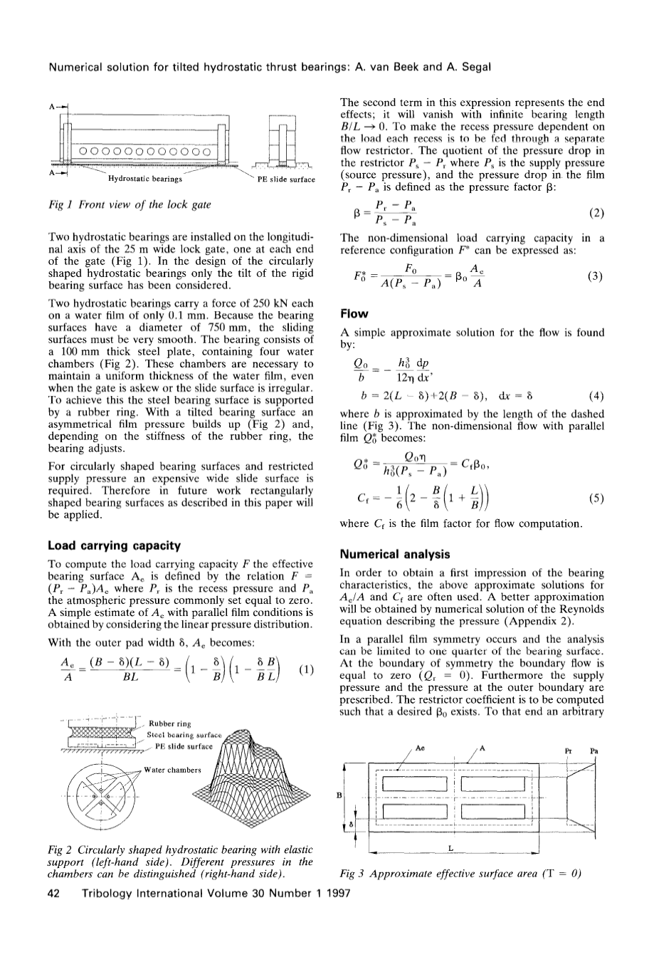
on a water film of only 0.1 mm. Because the bearing surfaces have a diameter of 750 mm, the sliding surfaces must be very smooth. The bearing consists of a 100 mm thick steel plate, containing four water chambers (Fig 2). These chambers are necessary to maintain a uniform thickness of the water film, even when the gate is askew or the slide surface is irregular. To achieve this the steel bearing surface is supported by a rubber ring. With a tilted bearing surface an asymmetric film pressure builds up (Fig 2) and, depending on the stiffness of the rubber ring, the bearing adjusts.
For circularly shaped bearing surfaces and restricted supply pressure an expensive wide slide surface is required. Therefore in future work rectangularly
B
Flow
A simple approximate solution for the flow is found
by:
b = 2(L — 6) 2(B 6 ) , 6x —— 6 (4)
where b is approximated by the length of the dashed line (Fig 3). The non-dimensional flow with pareira film Q becomes:
shaped bearing surfaces as described in this paper will — 6 2 lsquo; B
be applied.
Load carrying capacity
To compute the load carrying capacity I the effective
where C is the film factor for flow computation.
Numerical analysis
bearing surface As is defined by the relation F
_ In order to obtain a first impression of the bearing
(P, — P )A where P is the recess pressure and P the atmospheric pressure commonly set equal to zero. A simple estimate of A with parallel film conditions is obtained by considering the linear pressure distribution.
With the outer pad width 6, As becomes:
(8 — 6)(L —— 6) 6 B BL B B L
characteristics, the above approximate solutions for GA and Cf are often used. A better approximation will be obtained by numerical solution of the Reynolds
equation describing the pressure (Appendix 2).
In a parallel film symmetry occurs and the analysis can be limited to one quarter of the bearing s'Uni Iaccoca. At the boundary of symmetry the boundary flow is equal to zero ( Q, = 0). Furthermore the supply pressure and the pressure at the outer boundary are prescribed. The restrict-or coefficient is to be computed such that a desired Q exists. To that end an arbitrary
chosen value 5 is taken. The real value y will be derived from the computed pressure distribution. The procedure
is illustrated in diagram DI).
With the pressure distribution based off 7o °$VD, theacute; pressure factor Q and the restrict-or flow can be
Compares. ii Orifice: restriction is crappie sic:n:
(6)
Now the restrict-or coefficient y based on the desired press are factor Q can be computed:
(7)
of take restrict-or coefficient does not need the flow
computation derived from the film pressure.
Integration of the pressure distribution yields the load carry ing capacity and subsequently Arsquo;.
Both the numerically computed A Al and the analytic
Fig 5 Film factor Cf
From now on the bearing characteristics in the reference configuration ( Qq,/i,) are defined. Because As GA and Cl are, in the case of
剩余内容已隐藏,支付完成后下载完整资料
英语原文共 6 页,剩余内容已隐藏,支付完成后下载完整资料
资料编号:[150207],资料为PDF文档或Word文档,PDF文档可免费转换为Word

