英语原文共 8 页
A 6.25Gbps Feed-forward Equalizer in 0.18mu;m CMOS Technology for SerDes
Abstract—This paper presents a 6.25Gbps feed-forward equalizer (FFE) to reduce the inter-symbol-interference (ISI) in high-speed transmission backplane.
摘要——本文介绍了一个用于减少高速背板传输码间干扰的6.25Gbps前向反馈均衡器(FFE)。
The 3-tap fractionally spaced equalizer consists of a delay line, multiplier amp; summer cells and an output circuit.
该3抽头微间隔均衡器包含一个延时线、一个乘加单元以及一个输出电路。
Active-inductive peaking circuit and capacitor-degenerated circuit are used in the delay line and the output stage respectively to meet the bandwidth demand.
延迟线和输出级分别使用了电感并联峰化技术以及电容中和技术以满足带宽需求。
The proposed FFE has been implemented in TSMC 0.18mu;m CMOS technology with a whole area of 0.5mmtimes;0.51mm including I/O pads. The power consumption of the core circuit is 31.7mW under 1.8V power supply.
本文所设计的前馈均衡器使用台积电0.18mu;m CMOS工艺实现,包含I/O焊盘在内的芯片面积为0.5mmtimes;0.51mm,芯片核心电路功耗在1.8V供电下为31.7mW。
Post simulation results show that the distorted signal through a 24-inch backplane is well recovered by this equalizer.
后仿真结果表明,该均衡器能较好地恢复因经过24英寸背板而畸变信号。
Keywords-feed-forward equalizer (FFE); fractionally spaced equalizer (FSE); delay line cell; current mode logic (CML); active-inductive peaking; capacitor-degenerated
关键词:前向反馈均衡器(FFE);微间隔均衡器(FSE);延时线单元;电流模逻辑;有源电感峰化;电容中和
I. INTRODUCTION
With the ever-growing demand of high transmission rate in legacy backplane, many challenges have come to arise. The adjacent channel interference and the skin effect as well as dielectric interference in high-speed transmission backplane lead to the non-ideal characteristics of data transmission, which contributes to the inter-symbol interference (ISI).
对传统背板传输速率要求的不断提高引出了许多的设计挑战。高速背板传输中的相邻信道干扰、肤效应以及介质干扰导致了数据传输的非理想特性,导致了码间干扰(ISI)。
The ISI increases the bit error rate, resulting in the closure of the eye diagram. Thus, channel compensation technique, namely channel equalization must be taken into consideration in high-speed backplane data transmission.
码间干扰增加了误比特率,也导致了传输信号眼图的闭合。因此,高速背板数据传输必须考虑信道补偿技术,即信道均衡技术。
In a 6.25Gbps SerDes (serializer/deserializer), the received signal is so severely distorted after passing through the backplane that the subsequent circuits canrsquo;t work properly. This makes the equalizer a necessity in the receiver end of a SerDes.
在6.25Gbps的串化-解串器中,经过背板之后的接收信号会发生严重的畸变以至于后级电路无法正常工作。因此串化-解串接收机当中必需要有均衡器的存在。
There are two types of equalizer in the receiver: feed-forward equalizer (FFE) and decision feedback equalizer (DFE). FFE can eliminate both pre-cursor and post-cursor ISI and is simpler in structure compared to DFE. Most important is that it has no error propagation. But FFE may increase noise when it eliminates the ISI and its performance is not that good when dealing with a seriously distorted channel.
在接收机端有2种类型的均衡器:前向反馈均衡器(FFE)以及判决反馈均衡器(DFE)。和判决反馈均衡器相比,前向反馈均衡器既可以消除前标码间干扰,又可以消除后标码间干扰,并且拥有更简单的结构,最重要的是,前向反馈均衡器没有错误传输的问题。但是前向纠错均衡器在消除码间干扰的同时会引入额外的噪声,而且前向纠错均衡器对于导致失真严重的信道均衡效果不是很好。
In practice, FFE and DFE are used together for better equalization performance. This paper proposes a 6.25Gbps FFE in receiver.
在实际应用中,前向反馈均衡器和判决反馈均衡器的结合使用可以获得更好的均衡性能。本文设计了一个6.25Gbps带有前向反馈均衡器的接收机。
II. ARCHITECTURE
A. FFE Principle
A. 前向反馈均衡器原理
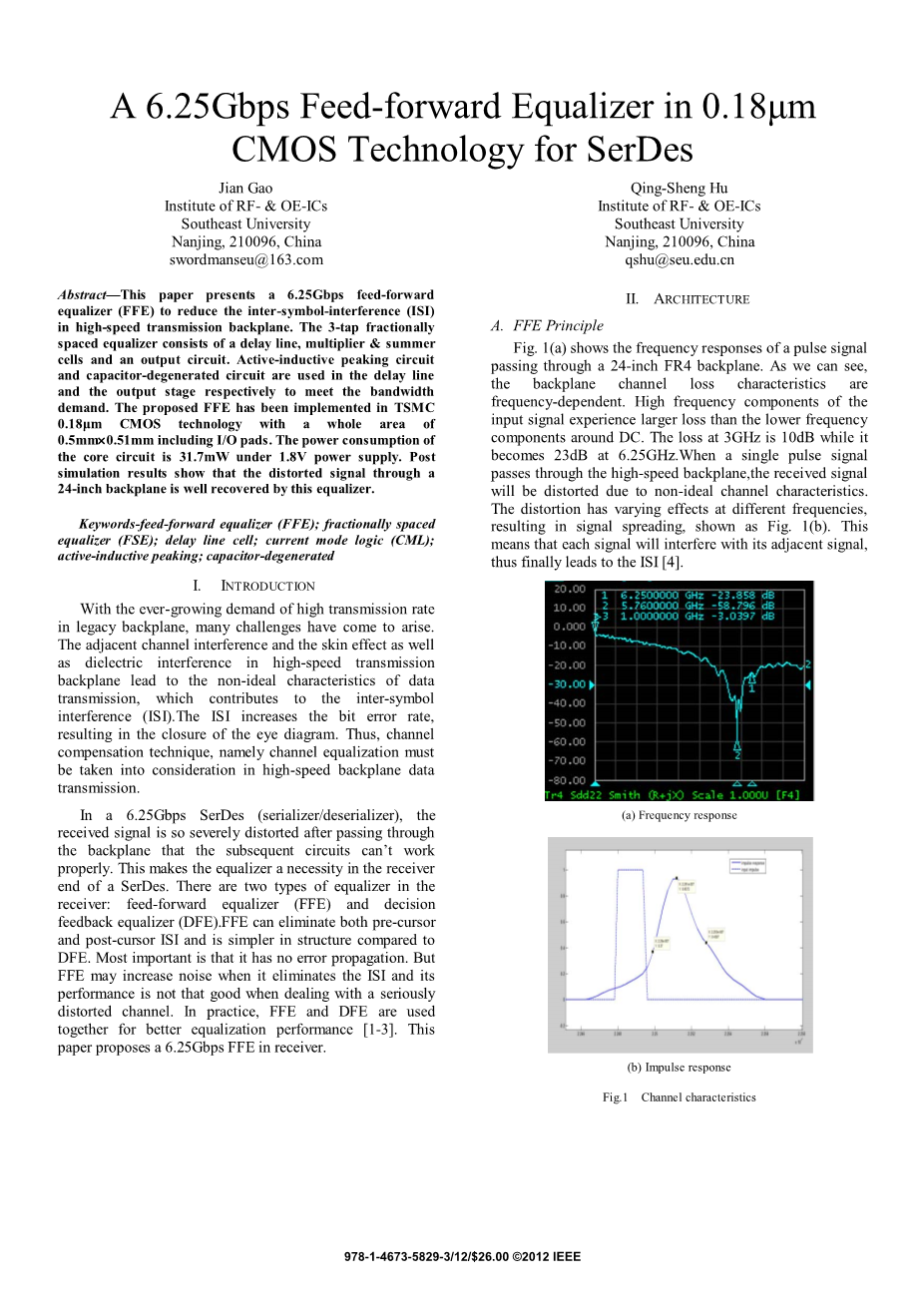
Fig. 1(a) shows the frequency responses of a pulse signal passing through a 24-inch FR4 backplane. As we can see, the backplane channel loss characteristics are frequency-dependent. High frequency components of the input signal experience larger loss than the lower frequency components around DC.
图1(a)显示了脉冲信号通过24英寸FR4背板的频率响应。可以看出,背板信道损耗特性是频率相关的。输入信号的高频成分相较于在直流附近的低频成分会经历更大的衰减。
The loss at 3GHz is 10dB while it becomes 23dB at 6.25GHz.
信号在3GHz的时候其衰减为10dB而到了6.25GHz其衰减变为了23dB。
When a single pulse signal passes through the high-speed backplane, the received signal will be distorted due to non-ideal channel characteristics.
当单个的脉冲信号经过背板时,接收信号会因为信道的非理想性而发生畸变。
The distortion has varying effects at different frequencies, resulting in signal spreading, shown as Fig. 1(b). This means that each signal will interfere with its adjacent signal, thus finally leads to the ISI.
畸变在不同频率下产生不同的影响,导致信号的拖尾,如图1(b)所示。这意味着每个信号都会干扰其相邻的信号,从而最终导致ISI。
An FFE can be treated as a transversal filter with 2N delay units and 2N 1 tap coefficients. Thus, impulse response for an FFE can be denoted as: (equation)
一个前向反馈均衡器可以看作一个拥有2N个延时单元和2N 1抽头系数的横向滤波器。因此前向反馈均衡器的脉冲响应可以表示为:(公式)
Where delta;(t) and q(t) are the input and output signal respectively, cK is the K-th coefficient and N is the number of the taps.
式种delta;(t)和q(t) 分别为输入信号和输出信号。cK为第K项的系数,N是抽头数量。
Let y(t) represent the input signal, then we can express output signal z(t) as following: (equation). Where “*” denotes convolution.
让y(t)代表输入信号,我们可以将输出信号z(t)表征为:(公式)。式中“*”表示卷积
To eliminate the ISI before and after the sampling time, suitable tap coefficients cK should be selected correctly. Normally, assume the pulse waveform at the equalizer are the same, we have: (equation). It means, in an ideal circumstance, an FFE could cancel the ISI completely if N is infinity
为了消除采样前后的ISI,需要正确选择合适的抽头系数以及各项前的系数cK。一般情况下,如果假设均衡器输入的脉冲波形相同,则有:(公式)。这意味着在理想情况下,如果抽头系数N趋近于无穷大,则一个前向反馈均衡器能完全消除码间干扰。
B. Architecture
B. 结构
In practical, a fractionally spaced equalizer (FSE) is often used instead of a baud spaced equalizer (BSE). They share the same theory, but FSE can effectively compensate for more severe distortion and deal with amplitude distortion with less noise enhancement.
在实际工程当中,经常被使用的是微间隔均衡器而不是波特间隔均衡器。他们有相同的理论基础但是微间隔均衡器可以有效地补偿较严重的失真,并在较低的噪声增强下处理幅度失真。
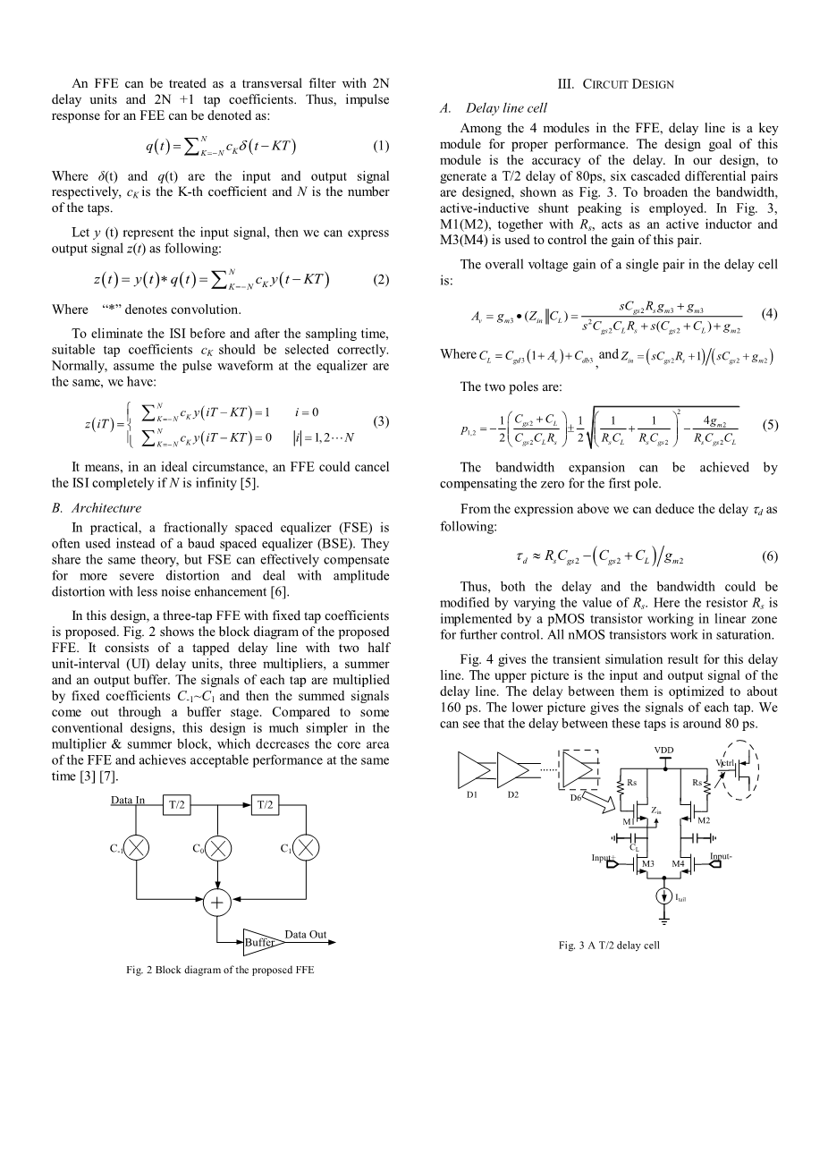
In this design, a three-tap FFE with fixed tap coefficients is proposed. Fig. 2 shows the block diagram of the proposed FFE. It consists of a tapped delay line with two half unit-interval (UI) delay units, three multipliers, a summer and an output buffer.
本文设计了

