LM628/LM629 Precision Motion Controller
Check for Samples: LM628, LM629
FEATURES
bull; 32-bit Position, Velocity, And Acceleration Registers
bull; Programmable Digital PID Filter with 16-bit Coefficients
bull; Programmable Derivative Sampling Interval
bull; 8- or 12-bit DAC Output Data (LM628)
bull; 8-bit Sign-magnitude PWM Output Data (LM629)
bull; Internal Trapezoidal Velocity Profile Generator
bull; Velocity, Target Position, and Filter Parameters may be Changed During Motion
bull; Position and Velocity Modes of Operation
bull; Real-time Programmable Host Interrupts
bull; 8-bit Parallel Asynchronous Host Interface
bull; Quadrature Incremental Encoder Interface with Index Pulse Input
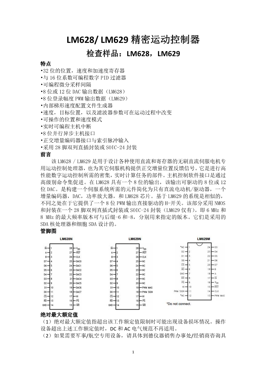
bull; Available in a 28-pin Dual In-line Package or a SOIC-24 Package
DESCRIPTION
The LM628/LM629 are dedicated motion-control processors designed for use with a variety of DC and Registers brush less DC servo motors, and other servomechanisms which provide a quadrature incremental position feedback signal. The parts perform the intensive, real-time computational tasks required for high performance digital motion control. The host control software interface is facilitated by a high-level command set. The LM628 has an 8-bit output which can drive either an 8-bit or a 12-bit DAC. The components required to build a servo system are reduced to the DC motor/actuator, an incremental encoder, a DAC, a power amplifier, and the LM628. An LM629-based system is similar, except that it provides an 8-bit PWM output for directly driving H-switches. The parts are fabricated in NMOS and packaged in a 28-pin dual in-line package or a SOIC-24 package (LM629 only). Both 6 MHz and 8 MHz maximum frequency versions are available with the suffixes -6 and -8, respectively, used to designate the versions. They incorporate an SDA core processor and cells designed by SDA.
Connection Diagrams
Absolute Maximum Ratings
(1) Absolute Maximum Ratings indicate limits beyond which damage to the device may occur. DC and AC electrical specifications do not apply when operating the device beyond the above Operating Ratings.
(2) If Military/Aerospace specified devices are required, please contact the Texas Instruments Sales Office/Distributors for availability and specifications.
(3) When operating at ambient temperatures above 70°C, the device must be protected against excessive junction temperatures. Mounting the package on a printed circuit board having an area greater than three square inches and surrounding the leads and body with wide copper traces and large, uninterrupted areas of copper, such as a ground plane, suffices. The 28-pin DIP (N) and the 24-pin surface mount package (M) are molded plastic packages with solid copper lead frames. Most of the heat generated at the die flows from the die, through the copper lead frame, and into copper traces on the printed circuit board. The copper traces act as a heat sink. Double-sided or multi-layer boards provide heat transfer characteristics superior to those of single-sided boards.
THEORY OF OPERATION
INTRODUCTION
The typical system block diagram illustrates a servo system built using the LM628. The host processor communicates with the LM628 through an I/O port to facilitate programming a trapezoidal velocity profile and a digital compensation filter. The DAC output interfaces to an external digital-to-analog converter to produce the signal that is power amplified and applied to the motor. An incremental encoder provides feedback for closing the position servo loop. The trapezoidal velocity profile generator calculates the required trajectory for either position or velocity mode of operation. In operation, the LM628 subtracts the actual position (feedback position) from the desired position (profile generator position), and the resulting position error is processed by the digital filter to drive the motor to the desired position.
POSITION FEEDBACK INTERFACE
The LM628 interfaces to a motor via an incremental encoder. Three inputs are provided: two quadrature signal inputs, and an index pulse input. The quadrature signals are used to keep track of the absolute position of the motor. Each time a logic transition occurs at one of the quadrature inputs, the LM628 internal position register is incremented or decremented accordingly. This provides four times the resolution over the number of lines provided by the encoder. See Each of the encoder signal inputs is synchronized with the LM628 clock.The optional index pulse output provided by some encoders assumes the logic-low state once per revolution. If the LM628 is so programmed by the user, it will record the absolute motor position in a dedicated register (the index register) at the time when all three encoder inputs are logic low.If the encoder does not provide an index output, the LM628 index input can also be used to record the home position of the motor. In this case, typically, the motor will close a switch which is arranged to cause a logic-low level at the index input, and the LM628 will record motor position in the index register and alert (interrupt) the host processor. Permanently grounding the index input will cause the LM628 to malfunction.
VELOCITY PROFILE (TRAJECTORY) GENERATION
The trapezoidal velocity profile generator computes the desired position of the motor versus time. In the position mode of operation, the host processor specifies acceleration, maximum velocity, and final position. The LM628 uses this information to affect the move by accelerating as specified until the maximum velocity is reached or until deceleration must begin to stop at the specified final position. The deceleration rate is equal to the accele
剩余内容已隐藏,支付完成后下载完整资料
英语原文共 6 页,剩余内容已隐藏,支付完成后下载完整资料
资料编号:[148565],资料为PDF文档或Word文档,PDF文档可免费转换为Word

