Man#39;s efforts to control ever-increasing quantities of power, mass, and speed with correspondingly greater precision has led to the rapid growth of the fluid control field. The convenience of attaining high power-to-weight ratios has rocketed hydraulic servo mechanisms into prominence wherever precise motion control is to be accomplished and where space and weight are limited.
In many control systems the hydraulic servo is the final high force or power component which receives a low-power electrical input signal and translates it into a high energy, easily controlled output. This increase in controlled power level may be accomplished in one stage of amplification of progressively increasing power levels.
In equally as many systems, the entire control may use only mechan-ical-hydraulic components. The input to these control systems may be supplied by mechanical transducers which can be used to sense various control parameters such as position, force, speed, pressure, or temperature.
The resulting complete system employing either mechanical-hydraulic or electrohydraulic components may be used for precise position control as in the case of machine tools. It may also involve the control of rates of turning, climbing, or rolling of aircraft, missiles, and submarines. As a governor, the combined control components can be used to regulate the rotational speed of steam or gas turbines, internal combustion engines, and variable-ratio transmissions where the final speed-control actuating components demand both the high force and fast response that only a hydraulic servo can supply.
Electromagnetic signals transmitted across hundreds of miles of space be transformed by electronics or solid-state converters to supply electrical command signals for execution by hydraulic power actuators. Such is the case in missile-guidance controls, in automatic airplane landing approach systems, and in radar tracking equipment. Still in other cases, the human operator may impose his commands directly on the hydraulic servo actuators by mechanical means as in the case of the automotive power steering, the power shovel, or the airplane flight control.
In many of these system functions, electrical, electronic, mechanical, and pneumatic control components perform together with hydraulic servo controls in a division of tasks best suited to provide the required over-all system with accuracy, dynamic performance, and efficiency within the alloted system weight, space, and cost. Regardless of the end use, the hydraulic servo components must closely match the elements preceding them in the chain of command and then must perform the assigned output function precisely during both steady-state and transient operation. The control engineer has the job of effecting this match.
He can do this by establishing complete specifications for the hydraulic servo components and then by selecting the proper components that will provide these desired functions in every detail. In order to make the proper selection, there must be complete familiarity with the various types of hydraulic control components as well as their steady-state and dynamic characteristics.
Every component type has its own particular features and limitations, such as hysteresis, dead band, threshold signal level, nonlinearities, or in the case of hydraulic motors, torque ripple and breakaway torque losses.
However in every control application, there will be given types of hydraulic components and elements that will be the optimum or best suited for the given function. Even then, these elements must be combined in such a way as to give the desired result as well as the over-all matching with the characteristics of the other system components. In order to better identify these hydraulic control components, they may be classified as to the function that they perform in the control circuit, such as controlling components and conversion units.
The controlling components, such as valves and variable-displacement pumps, are used to generate or regulate controlled fluid power. This controlled fluid power is then converted to mechanical power to drive a given load. This function may be performed by pistons, rotary actuators, fixed-displacement motors, or any of the various types of turbines.
The variable-displacement motor, as discussed in Sec.6.3, combines both functions of control and conversion since its ability to convert fluid power to mechanical power may be directly adjusted by a change in displacement. Although not usually classed as a component, the fluid with its characteristics enters prominently into hydraulic servo work.
It provides the connection between the hydraulic components and in a way performs the function of a component. Therefore, its characteristics ae applied to servo work will be included in the following sections along with the important servo characteristics of the various hydraulic components.
In order to determine the transient or dynamic characteristic of a hydraulic control circuit, the complete characteristics of each component must be known. These characteristics may be given as constants or gradients-or in case of significant nonlinearities, a complete family of curves may be required. The following sections show how the general characteristics of the basic hydraulic components may be obtained, and how certain characteristic constants and gradients for the components may be derived from these general characteristics. It is this basic information that is required not only in the designing of hydraulic control components but also for the proper selection of the right servo components and control circuits which will result in optimum over-all system performance.
1.1. CONTROL VALVES
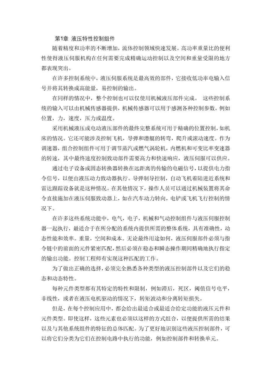
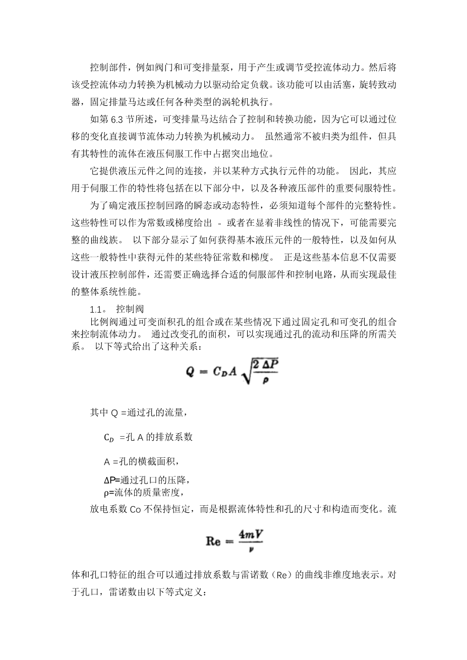
Proportional valves provide control of fluid power by a combination of variable-area orifices or in some cases by a combination of both fixed and variable orifices. By varying
英语原文共 21 页
资料编号:[3490]

