附件2:外文原文
8-2, Simple Beam Layout
The layout of a simple prestressed-concrete beam is controlled by two critical sections: the maximum moment and the end sections. After these sections are designed, intermediate ones can often be determined by inspection but should be separately investigated when necessary. The maximum moment section is controlled by two loading stages, the initial stage at transfer with minimum moment MG acting on the beam and the working-load stage with maximum design moment MT. The end sections are controlled by area required for share resistance, bearing plates, anchorage spacings, and jacking clearances. All intermediate sections are designed by one or more of the above requirements, depending on their respective distances from the above controlling sections. A common arrangement for posttensioned members is to employ some shape, such as I or T, for the maximum moment section and to round it out into a simple rectangular shape near the ends. This is commonly referred to as the end block for posttensioned members. For pretensioned members, produced on a long line process, a uniform I, double-T, or cored section is employed throughout, in order to facilitate production. The design for individual sections having been explained in Chapters 5, 6, and 7,the general cable layout of simple beams will now be discussed.
The layout of a beam can be adjusted by varying both the concrete and the steel. The section of concrete can be varied as to its height, width, shape, and the curvature of its soffit or extrados. The steel can be varied occasionally in its area but mostly in its position relative to the centroidal axis of concrete. By adjusting these variables, many combinations of layout are possible to suit different loading conditions. This is quite different from the design of reinforced-concrete beams, where the usual layout is either a uniform rectangular section or a uniform T-section and the position of steel is always as near the bottom fibers as is possible.
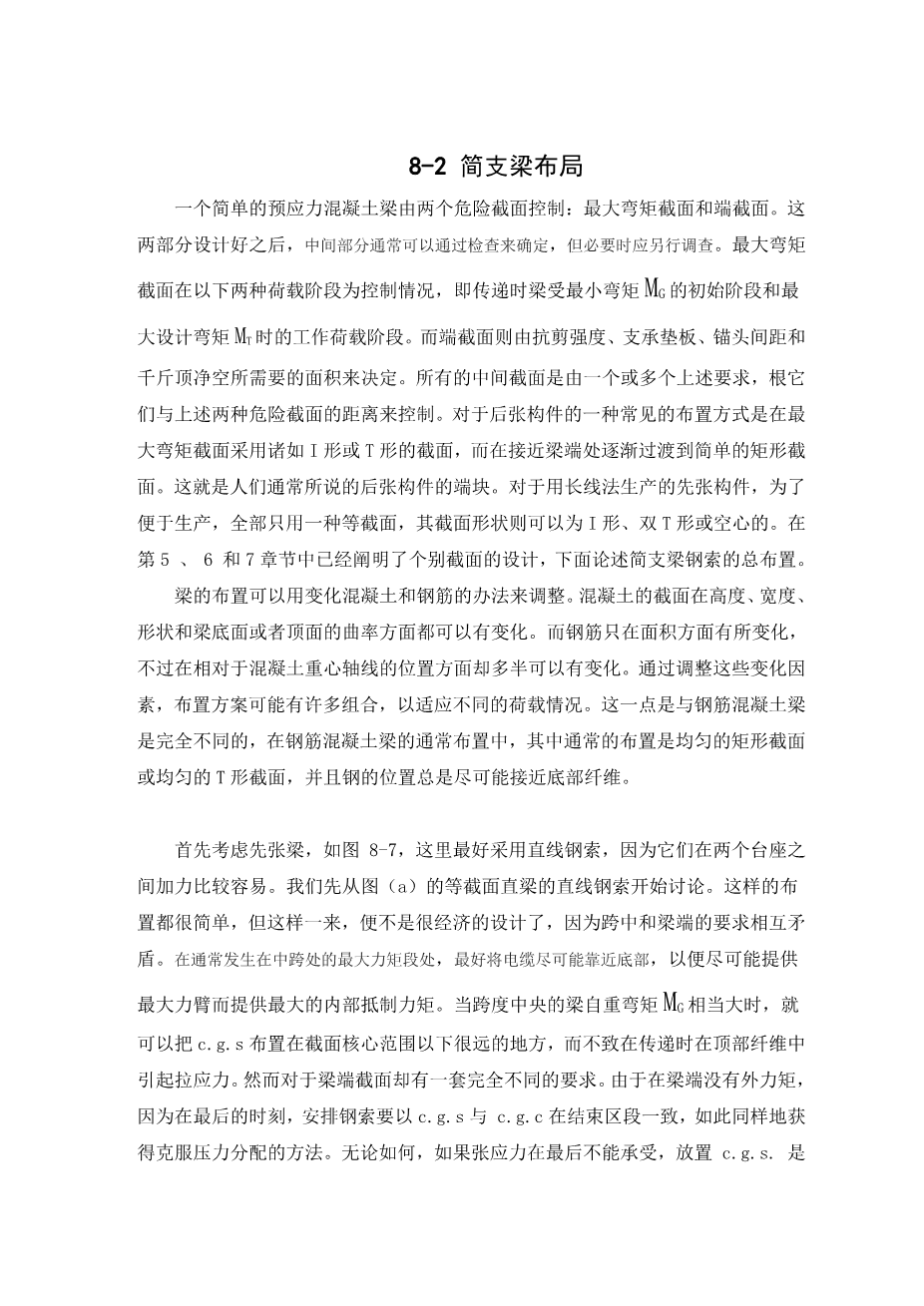
Consider first the pretensioned beams, Fig. 8-7.Here straight cables are preferred, since they can be more easily tensioned between two abutments. Let us start with a straight cable in a straight beam of uniform section, (a).This is simple as far as form and workmanship are concened, But such a section cannot often be economically designed, because of the conflicting requirements of the midspan and end sections. At the maximum moment section generally occurring at midspan, it is best to place the cable as near the bottom as possible in order to provide the maximum lever arm for the internal resisting moment. When the MG at midspan is appreciable, it is possible to place the c. g. s. much below the kern without producing tension in the top fibers at transfer. The end section, however, presents an entirely different set of requirements. Since there is no external moment at the end, it is best to arrange the tendons so that the c. g. s. will coincide with the c. g. c. at the end section, so as to obtain a uniform stress distribution. In any case, it is necessary to place the c. g. s. within the kern if tensile stresses are not permitted at the ends, and not too far outside the kern to avoid tension stress in excess of allowable values.
It is not possible to meet the conflicting requirements of both the midspan and the end sections by a layout such as ( a ). For example, if the c. g. s. is located all along the lower kern point, which is the lowest point permitted by the end section, a satisfactory lever arm is not yet attained for the internal resisting moment at midspan. If the c. g. s. is located below the kern, a bigger lever arm is obtained for resisting the moment at midspan, but stress distribution will be more unfavorable at the ends. Besides, too much camber may result from such a layout, since the entire length of the beam is subjected to negative bending due to prestress. In spite of these objections, this simple arrangement is often used, especially for short spans.
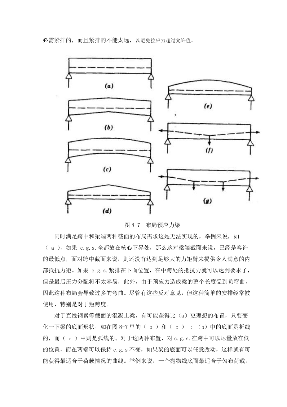
Fig 8-7. Layouts for pretensioned beams.
For a uniform concrete section and a straight cable, it is possible to get a more desirable layout than ( a ) by simple varying the soffit of the beam, as in Fig. 8-7( b ) and ( c ); ( b ) has a bent soffit, while ( c ) has a curved one. For both layouts, the c. g. s. at midspan can be depressed as low as desired, while that at the ends can be kept near the c. g. c. If the soffit can be varied at will, it is possible to obtain a curvature that will best fit the given loading condition; for example, a parabolic soffit will suit a uniform loading. While these two layouts are efficient in resisting moment and favorable in stress distribution, they possess three disadvantages. First, the formwork is more complicated than in ( a ). Second, the curved or bent soffit is often impractical in a structure, for architectural or functional reasons. Third, they cannot be easily produced on a long-line pretensioning bed.
When it is possible to vary the extrados of concrete, a layout like Fig. 8-7( d ) or ( e ) can be advantageously employed. These will give a favorable height at midspan, where it is most needed, and yet yield a concentric or nearly concentric prestress at end section. Since the depth is reduced for the end sections, they must be checked for share resistance. For ( d ), it should also be noted that the critical section may not be at midspan but rather at some point away from it where the depth has decreasd appreciably while the external moment is still near the maximum. Beam ( d ), however, is simple in formwork than ( e ), which has a curved extrados.
Most pretensioning plants in the United States have buried anchors along the stressing beds
剩余内容已隐藏,支付完成后下载完整资料
英语译文共 7 页,剩余内容已隐藏,支付完成后下载完整资料
资料编号:[467960],资料为PDF文档或Word文档,PDF文档可免费转换为Word

